TALES
OF TWO TRANSMITTERS RESCUES OF CLASSIC BROADCAST RIGS Page 1 — Continental Electronics 314R1 |
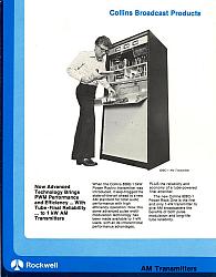 1. 314R1 brochure | My
first rescue of a broadcast transmitter was for a Continental 314R1
"Power Rock" that was on 1230 KHz at KVOC in Casper, WY. I
had the brochure from 1980, and couldn’t resist taking it on. Take a
look at the stylish geek sticking his hand inside the fold-down control
board. The 230 VAC circuit breakers and filament rheostats are also on
the panel, so I wouldn't recommend reading the manual while poking
around like this. I remember
the Power Rock 5 Kw model being a loud and impressive rig, but also
very dangerous to work on, having -13 kV DC supply inside.
Rockwell/Collins
Broadcast sold their transmitter line to Continental Electronics in
Dallas, and the 828C1 became the 314R1 in their model numbering scheme.
It was their last kW rig with tubes, following the 820D2. Collins
advertising mentions the advantages of using three 3-500Z triodes over
the solid state models (Harris MW1 was a target). Harris was about to
unleash their SX series of PWM rigs with MOSFETs. The 314R1 was already
packing PWM, with 3 glorious tubes. Some called it the Power Pebble,
leaving the name Power Rock for it’s popular 5 KW
sibling. (Click on
any photo to enlarge.) |
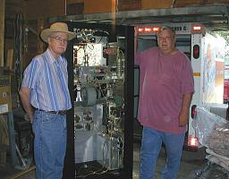 2. W5JO and K7KMT with 314R1, sans plate transformer, ready to tip it over | I
made the 1240 mile roundtrip to Casper on June 26-28 of 2003.
It
took me all
day, leaving Santa Fe county, NM at daybreak and finding a motel in
Casper after
dark. Jim Wilhite (W5JO) met me at the garage of engineer Steve Fritz
(K7KMT) the next morning, where the transmitter was waiting next to his
BC1T. I
immediately removed all of the iron from the base, after taping and
marking the leads. The plate transformer on this rig is a beast, since
it supplies -8500 volts for the switch tube, ‘totem pole’
connected in series with the cathodes of the RF tubes. It has no choke,
only a large capacitor. This improves resistance to HV 'bounce' at low
audio frequencies, and incipient carrier shift or overmodulation that
it can create. The
tubes
came out into boxes. I had already built a dolly in advance, from two
sheets of � inch plywood with carriage bolts and four casters, so it
was relatively easy to roll it over to the U-Haul trailer I had rented
– I didn’t want this gorgeous transmitter to get beat up in the
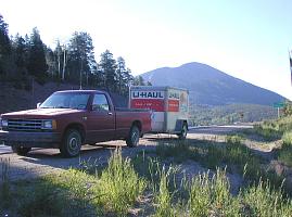
weather. | 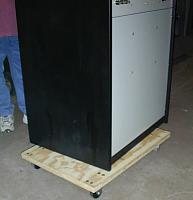 3. 314R1 on dolly |
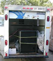 4. Packed trailer - ready to roll |
After
having lunch with the guys, I bade them 73 and headed south, across WY,
and reached Loveland, CO where I noticed the radiator hose ready to
rupture on our 1985 Chevy S10. I had warning that it was going
as
the temperature
was rising as it lost coolant, so I nursed it along on the frontage
road, and was able to roll into a NAPA parts store where I bought the
proper hose, and replaced it myself. Good thinking to bring a full set
of tools. I got around Denver during rush-hour traffic, staying in
motel near
Walsenburg, CO. My transmitter was safe in the locked trailer.. |
 5.
Early morning over La Veta Pass, CO | Early the next morning I made the last miles back to my QTH in northern New Mexico. The photo shows crossing La Veta Pass at 9413 feet elevation, at 7:30 in the morning. Avoiding the summer heat kept our old 6 cylinder engine happy. Also, it kept me cooler since the old truck lacked A/C. | 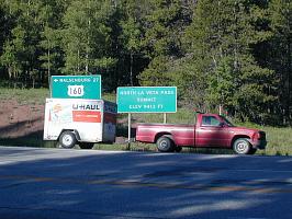 6. We made it |
Once the transmitter was home, I began to put it back into working condition on the original frequency - always a good idea before starting to modify something. Clean up was accomplished in our carport, before it was rolled into the house for checkout. The transmitter had been around smokers (many radio stations have them), so I had to remove a lot of the tie wraps and use alcohol and water to clean the white silicon HV wire in the harnesses and all of the metal surfaces. This transmitter has a lot of components and subassemblies floating at HV, so cleanliness was important before hitting the power button. The worst crud was a sticky goo that had accumulated in the bottom of the blower beneath the tubes. The vacuum variable plate tuning capacitor was dissembled and lubricated. Once I installed the plate transformer and the Sola filament regulator, I applied 230 VAC. Tubes lit up, the cabinet fan sounded like an airplane, and the controls and interlocks behaved. Some troubleshooting ensued to find why the RF oscillator was gated off. I replaced the noisy Grainger 500 CFM cabinet fan with a less noisy Rotron Caravel fan, with a homemade housing of masonite. For less intermittent amateur operation, this should be adequate for the cabinet, as the tubes also have a dedicated 300 CFM squirrel cage blower. Later this proved to be true as I tested it at full power. The Caravel made much less racket, allowing me to test the 314R1 at all hours in my spare bedroom/hamshack.
With a sufficient dummy load connected, I applied HV. It was immediately followed by a plate overload tripout. I discovered that one of the HV transistors on the switch tube driver card was shorted. This was a common failure mode on Power Rocks. These parts are switching hundreds of volts at 70 KHz, to drive the 3-500Z into and out of hard conduction, and Continental had later made a design change to Hexfets, although the reliability and performance of the modification is questionable - according to at least one ex-Collins engineer. One thing is for certain, the patented PWM distortion compensation circuit has mica capacitors and resistors that must be chosen for the exact make of triode. Eimac and Amperex tubes require different compensation, as I learned from a bulletin from Continental. They were very helpful in providing me an updated schematic and parts list for the sections which had changed over the years. The voltage dividers on card A4 that drive the HV meter as well as providing audio feedback into the audio input section were cooked and had to be rebuilt with new resistors.
After all of this, it tried to run long enough to show the anode of the switch tube glowing nearly yellow, and a deep purple glow was seen on the glass. The HV breaker tripped this time. The clamping diode at the output of the PDM filter was shorted. This was what took the rig off the air in Casper. A call to Continental brought back the bad news that it was about $800 for a new one from Semtech. I got the specs from them, and began to search. I found a source for surplus fast recovery HV doorknob rectifiers, the HV Components Associates HGU2, which could be stacked to get 18 kV PRV at 10 Amps average current. Eventually the Power Rock was playing perfectly into my load. Other projects took precedence at home, so my 314R1 remains on 1230, not retuned up to 160 or 75 meters where I eventually want it to play. I have been collecting mica transmitter capacitors and information to move the output bandpass network (not a Pi-L or Tee as in many tube BC rigs) up in frequency. The driver stage, a pair of HV bipolar transistors running class D, will predictably be in trouble at 3.8 MHz so a MOSFET replacement is in the works.
For further information on the 314R1, here are some links (all in Adobe pdf format):
Schematic [in two parts, ~1 MB each] Page 1, Page 2
Description of How the Power Rock Modulates
Patents on the Power Rock US 04140980, US 04187467, US 04199723
Complete brochure [3.3 MB]